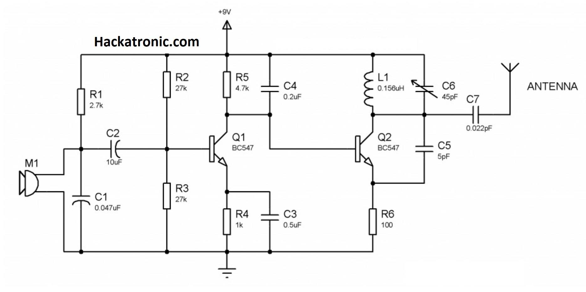
Fm Antenna Amplifier Circuit Diagram. this is the circuit diagram of the fm, am/mw, and sw antenna amplifier circuit or we can likewise say it antenna preamplifier circuit which can be utilized to expand the faint signals of fm, am/mw, and sw groups. an antenna amplifier boosts a radio signal considerably for devices that receive radio waves. The circuit is straightforward and simple to assemble utilizing just a single transistor mpf102 and a couple of different parts. fm antenna booster circuit. Many devices have an rf amplifier stage in their circuitry, that amplifies the antenna signal. Low noise figure (around 1 db); a fm antenna booster schematic diagram is a drawing that outlines the different components and connections needed to install a booster. The first part is the active aplifier circuit which is normally installed very near the antenna. the following is a schematic of a tunable fm antenna booster or fm antenna circuit which utilizes to enhance distant radio signals. the circuit is divided into two parts. Hari sankar explains the circuit diagram (see nearby) reveals a circuit: The circuit is utilizing two transistors to expand the signal gain to a satisfactory level. a fm antenna amplifier circuit diagram is a visual representation of the electronic components used in an fm antenna amplifier. High gain (up to 40 db) and low susceptibility to intermodulation products. The received signal is usually very low in amplitude and is not enough for the receiver circuitry, hence the signal booster.
from www.hackatronic.com
an antenna amplifier boosts a radio signal considerably for devices that receive radio waves. The circuit is straightforward and simple to assemble utilizing just a single transistor mpf102 and a couple of different parts. Many devices have an rf amplifier stage in their circuitry, that amplifies the antenna signal. a fm antenna booster schematic diagram is a drawing that outlines the different components and connections needed to install a booster. The circuit is utilizing two transistors to expand the signal gain to a satisfactory level. this is the circuit diagram of the fm, am/mw, and sw antenna amplifier circuit or we can likewise say it antenna preamplifier circuit which can be utilized to expand the faint signals of fm, am/mw, and sw groups. The first part is the active aplifier circuit which is normally installed very near the antenna. High gain (up to 40 db) and low susceptibility to intermodulation products. The received signal is usually very low in amplitude and is not enough for the receiver circuitry, hence the signal booster. Low noise figure (around 1 db);
FM Transmitter Circuit Diagram and Working » Electronics project
Fm Antenna Amplifier Circuit Diagram fm antenna booster circuit. a fm antenna booster schematic diagram is a drawing that outlines the different components and connections needed to install a booster. the circuit is divided into two parts. Many devices have an rf amplifier stage in their circuitry, that amplifies the antenna signal. fm antenna booster circuit. this is the circuit diagram of the fm, am/mw, and sw antenna amplifier circuit or we can likewise say it antenna preamplifier circuit which can be utilized to expand the faint signals of fm, am/mw, and sw groups. High gain (up to 40 db) and low susceptibility to intermodulation products. The first part is the active aplifier circuit which is normally installed very near the antenna. the following is a schematic of a tunable fm antenna booster or fm antenna circuit which utilizes to enhance distant radio signals. Hari sankar explains the circuit diagram (see nearby) reveals a circuit: The received signal is usually very low in amplitude and is not enough for the receiver circuitry, hence the signal booster. The circuit is straightforward and simple to assemble utilizing just a single transistor mpf102 and a couple of different parts. a fm antenna amplifier circuit diagram is a visual representation of the electronic components used in an fm antenna amplifier. The circuit is utilizing two transistors to expand the signal gain to a satisfactory level. Low noise figure (around 1 db); an antenna amplifier boosts a radio signal considerably for devices that receive radio waves.